
How to Select a CO₂ Revert Gas Recovery System for Dry Ice Production — Working Principle & Practical Sizing Guide
Meta Description: Understand how CO₂ recovery works for dry ice pelletizer / block dry ice machines, core technical indicators, capacity matching, bladder design, purity & safety standards, and the key checklist to pick the right recovery unit for your dry ice plant.
Published on Wainew Intelligent Equipment Blog
Introduction
In standard dry ice production, liquid CO₂ (LCO₂) expands inside the pelletizer or block dry ice press. Only 40–45% of the feed liquid CO₂ converts into solid dry ice; the remaining 55–60% flashes into low-pressure gaseous CO₂ (called revert CO₂ gas) and is normally vented to atmosphere, which represents huge raw material cost loss.
A dedicated CO₂ recovery system captures this flash revert gas, purifies, compresses, dries and re-liquefies it back into liquid CO₂, feeding it back into your dry ice production loop. With a properly matched recovery unit, your overall dry-ice-to-LCO₂ conversion ratio can rise to 90–95%, cutting liquid CO₂ procurement cost dramatically while lowering carbon emissions.
This guide is written specifically for dry ice plant owners, dry ice equipment distributors and plant engineers. It focuses only on revert gas recovery from dry ice production lines, not generic CO₂ capture from flue gas, biogas or fermentation sources.
1. Working Principle of Dry‑Ice CO₂ Recovery Equipment
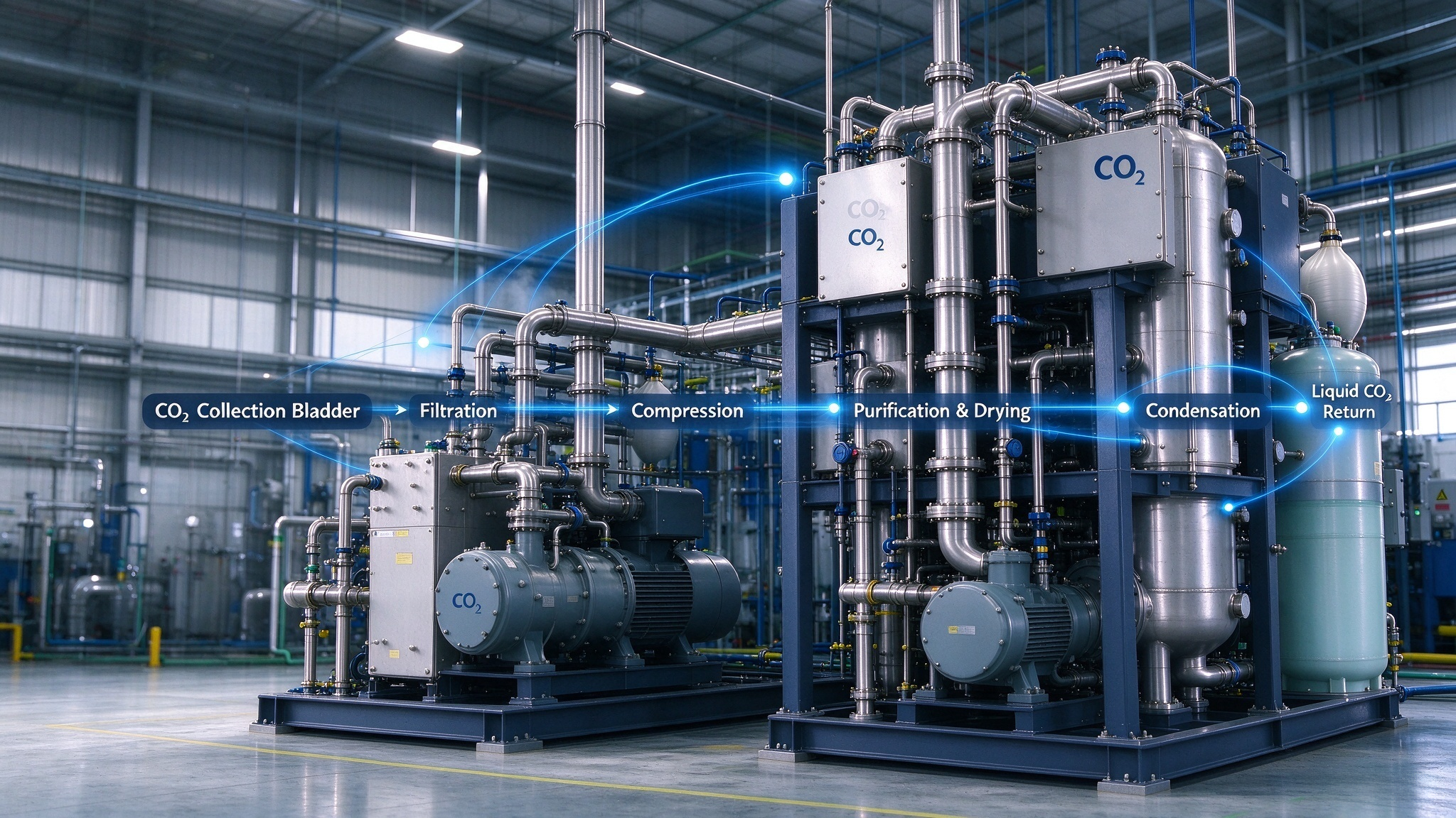
The full process flow for dry ice revert CO₂ recovery follows this fixed sequence:
- Gas collection stage: Low-pressure cold revert CO₂ gas discharged from the vent port of dry ice pelletizer / block press is first collected into a CO₂ gas collection bladder (or tank). The bladder acts as a buffer tank to balance unstable instantaneous gas flow from intermittent dry ice extrusion, avoiding surge and compressor hunting. This bladder must be low-permeability, low-temperature resistant, and sized to hold peak flash gas volume.
- Pre-filtering & pre-cooling: Crude CO₂ gas passes through demisters and coarse filters to remove dry ice dust, frost, condensate and fine solid particles carried over from the pelletizer.
- Compression: Multi-stage oil-free CO₂ compressor boosts gas pressure to the liquefaction setpoint (typically around 18 barg). Oil-free design is mandatory for food-grade CO₂ loops to avoid hydrocarbon contamination.
- Purification & dehydration: Activated carbon adsorption + molecular sieve drying removes moisture, trace oil vapour and non-condensable impurities (N₂, O₂). Dew point control here is critical; residual water will freeze inside heat exchangers and cause blockage.
- Refrigeration liquefaction: High-pressure dry CO₂ enters the refrigerated condenser. Under design pressure, CO₂ condenses back into liquid CO₂. Non-condensable gases are periodically purged.
- Liquid return & storage: Regenerated liquid CO₂ flows back into your existing insulated LCO₂ storage tank for reuse by dry ice machines, closing the production loop.
Important note: This system only recovers high-purity revert CO₂ gas from dry ice expansion. It cannot handle mixed flue gas, biogas or low-concentration CO₂ streams without extra front-end scrubbing modules.
2. Core Selection Logic: Match Recovery Capacity to Dry Ice Machine Output
This is the #1 mistake most buyers make: selecting a recovery unit smaller than the peak revert gas flow of their dry ice machines.
The physical rule:
Every 1 ton of dry ice produced generates approximately 1.2–1.4 tons of revert gaseous CO₂ to be recovered.
Practical capacity matching table for reference
| Dry ice machine rated output | Approx revert CO₂ gas generation | Recommended recovery system nominal capacity |
|---|---|---|
| 100 kg/h pelletizer | 120–140 kg/h revert gas | 150 kg/h recovery unit |
| 300 kg/h pelletizer | 360–420 kg/h revert gas | 400–450 kg/h recovery unit |
| 500 kg/h pelletizer | 600–700 kg/h revert gas | 700–750 kg/h recovery unit |
| Block dry ice press (200–400 kg/h) | 240–560 kg/h revert gas | 500–600 kg/h recovery unit |
Rules for sizing:
- If you run multiple dry ice machines in parallel, sum up the total peak revert gas, not average continuous output.
- Leave a 15–25% capacity margin for startup surge, unstable feeding and seasonal ambient temperature rise.
- Do not oversize excessively: oversized units run under low load frequently, leading to poor liquefaction efficiency and higher specific power consumption per ton of recovered CO₂.
3. Key Technical Parameters You Must Verify Before Purchase
3.1 Recovery rate & final CO₂ purity
- Target recovery rate for dry ice revert loop: ≥90% (industry mature standard; premium skids reach 93–95%).
- Output CO₂ purity: ≥99.90% for general industrial dry ice; ≥99.99% food grade for food-contact dry ice, dry ice used in pharmaceutical cold chain.
- Acceptable impurities: Water content ≤20 ppm; no residual oil; non-condensable gas fraction strictly controlled.
3.2 Specific power consumption (kWh per ton recovered CO₂)
This decides your long-term ROI. Reliable dry-ice dedicated recovery skids usually sit at 120–160 kWh / ton of recovered liquid CO₂. Units above 180 kWh/ton are considered inefficient and will erode your cost savings from CO₂ recycling.
3.3 Gas collection bladder specification
The CO₂ gas collection bladder (buffer bladder) is a critical auxiliary component often underestimated:
- Material: Low-temperature resistant, low CO₂ permeation membrane (PVC/TPU composite or fluorine fabric for premium versions). Ordinary air bags leak CO₂ quickly.
- Working pressure: Near-atmospheric, slight positive pressure (0.002–0.005 barg).
- Volume: Sized for 3–5 minutes of peak revert gas accumulation. Too small = frequent compressor start-stop and gas venting; too large = higher footprint and slow response.
- Safety feature: Overflow vent and low-level interlock to stop compressor when bladder is empty (prevent air suction into the loop).
3.4 Compressor type
Always choose oil-free dry-running CO₂ compressors for dry ice revert recovery. Lubricated oil-injected compressors risk oil contamination, which ruins CO₂ purity and causes fouling inside dry ice machines.
3.5 Refrigeration system
Two mainstream configurations: integrated cascade refrigeration or external chilled water cooling.
- Water-cooled: Lower running cost for sites with stable cooling water supply.
- Air-cooled skid: Plug-and-play, suitable for workshops without cooling water towers, but higher power draw in hot tropical climates (Southeast Asia, India, Middle East).
4. Compatibility & Integration Check List
Before ordering, confirm these compatibility items with your supplier:
- Can the unit connect directly to the vent piping of your existing pelletizer / block dry ice machine? What is the inlet flange size and working pressure?
- Control interlock: Does it support automatic linkage with dry ice machines? When pelletizer stops, recovery system automatically enters standby mode.
- Piping material: Stainless steel 304 / 316L for cold CO₂ gas path to avoid rust contamination.
- Pressure safety components: ASME / CE / PED certified pressure vessels, safety relief valves, rupture discs.
- Control system: Local HMI + remote signal output; alarms for high pressure, low bladder level, high dew point, compressor fault.
- Ambient adaptability: If your plant runs in high-temperature tropical areas (>35°C), ask the supplier to derate the capacity accordingly.
5. Different System Types & Who They Suit
- Modular skid-mounted bolt-on recovery system (Most popular for dry ice factories) Pre-assembled, tested on one skid, fast installation, suitable for retrofitting onto existing dry ice production lines. Wainew’s standard CO₂ recovery units belong to this category. Best for small-to-medium dry ice plants with 1–4 pelletizers.
- Large custom-built central recovery plant For high-volume dry ice factories with multiple block presses and pelletizers running continuously 24/7. Higher capital cost, better economy at very large throughput.
- Simplified low-budget recovery units Usually omit full deep purification; only suitable for non-critical industrial cleaning-grade dry ice, not food or pharma grade. Higher risk of impurity buildup inside your LCO₂ tank.
6. ROI & Economic Evaluation for Your Reference
Take a typical 300 kg/h dry ice line as an example:
- Without recovery: ~58% of liquid CO₂ is wasted.
- With matched recovery skid: Liquid CO₂ purchase consumption drops by ~45–50%.
- Payback period for qualified recovery systems in most dry ice plants is usually 12–24 months, highly dependent on local liquid CO₂ market price and running hours per year.
Important reminder: Do not judge only by upfront equipment price. A cheaper unit with high power consumption or low recovery rate may never reach positive ROI.
7. Common Pitfalls to Avoid
- Pitfall 1: Buying a recovery system designed for brewery/fermentation CO₂, not dry ice revert gas. Fermentation CO₂ contains alcohol vapour and different impurity profiles; these systems are not optimized for cold flash gas from pelletizers.
- Pitfall 2: Ignoring the bladder buffer and running compressor directly against unstable flash gas flow. This causes frequent venting, compressor damage and unstable recovery efficiency.
- Pitfall 3: Under-sizing because you only calculate average dry ice output instead of peak flash gas.
- Pitfall 4: Skipping dew point monitoring. Water ingress will freeze in heat exchangers, block pipelines and force frequent shutdown.
- Pitfall 5: Mixing air into the recovery loop. Air (non-condensable gas) accumulates inside the liquefier, reduces liquefaction efficiency and requires regular manual purging. Good systems have automatic non-condensable purge modules.
8. Final Selection Checklist (Quick Reference)
✅ Confirm total peak revert CO₂ gas flow from all dry ice machines
✅ Select nominal capacity with 15–25% safety margin
✅ Confirm oil-free compressor, SS gas pipeline, food-grade purification if required
✅ Check specific power consumption (target ≤160 kWh/ton recovered CO₂)
✅ Confirm bladder buffer sizing, material and pressure interlock
✅ Verify certification (CE, PED, pressure vessel approval)
✅ Check cooling mode: air-cooled or water-cooled match your site condition
✅ Confirm control interlock and alarm functions
✅ Ask supplier to provide on-site piping layout drawing before production
Conclusion
A well-matched CO₂ revert recovery system is one of the most valuable upgrades for dry ice manufacturers. The core of selection is not simply “buy a bigger machine”, but to size around the flash revert gas characteristic of your dry ice pelletizer or block press, with attention to buffer bladder design, purification performance, power consumption and site integration.
If you share your dry ice machine model, hourly output, local power supply and cooling condition, Wainew’s engineering team can provide custom capacity calculation and a tailored recovery layout proposal.
Author: Wainew Intelligent Equipment
Wainew focuses on R&D and manufacturing of dry ice pelletizers, block dry ice machines, dry ice blasting machines and supporting CO₂ recovery systems, with full independent intellectual property rights and CE export certification.